Building a better keyboard

I want a better keyboard but my plea to the industry had no effect. Since no one would make one for me I built the keyboard myself. My main goals were:
- Standard split-QWERTY layout mirroring the Microsoft Natural Keyboards
- No number pad
- High quality mechanical switches
- Bluetooth and USB-C connections
- Plug and play (no-solder) microcontroller replacement
Layout
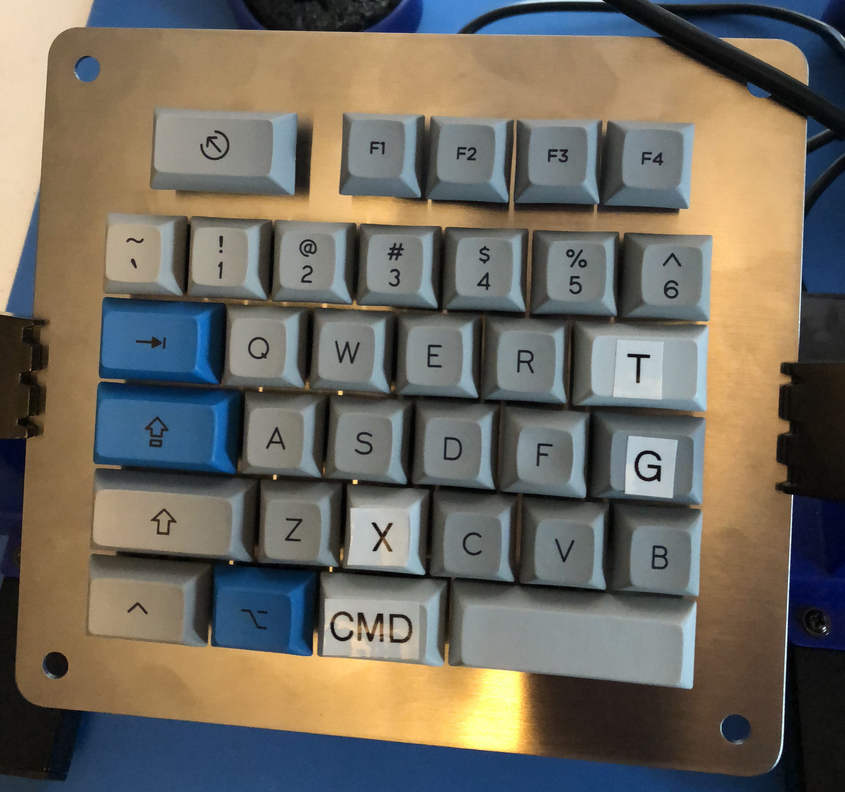
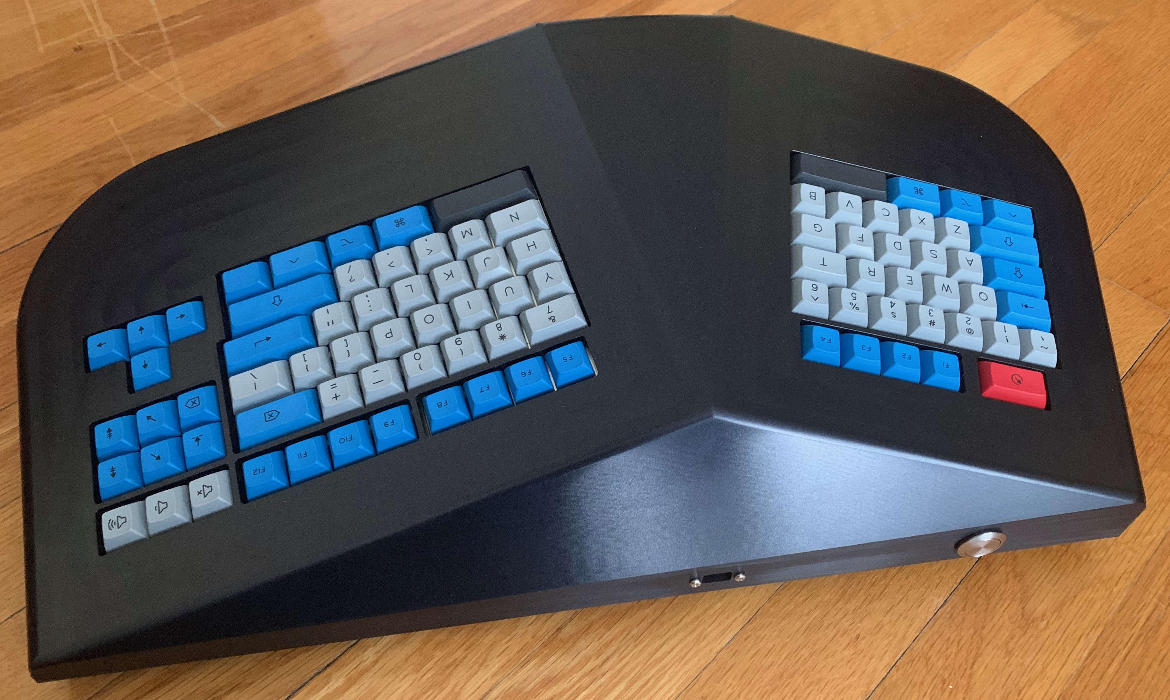
Building a keyboard naturally starts with designing the key layout. I used the wonderful Keyboard Layout Editor to build a tweaked version of the classic Microsoft Natural Keyboard layout.
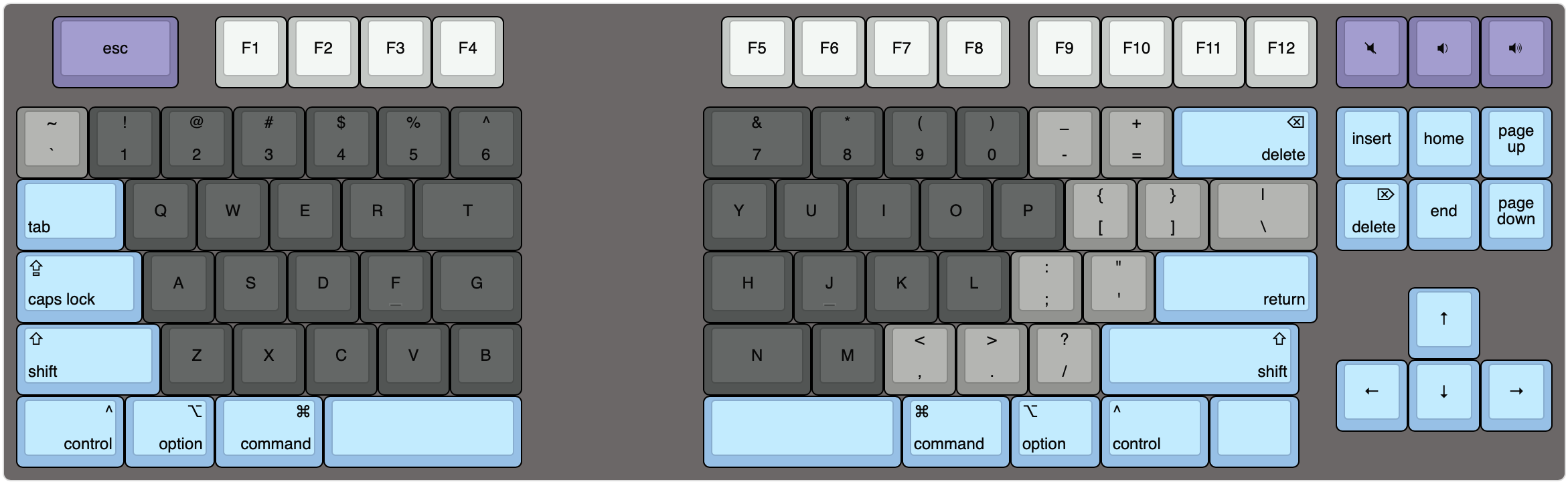
The big changes I made were a larger escape key for ease of vim and dedicated volume control keys since those are the only media keys I have ever used. Sorry Natural Keyboard Elite diehards: I kept the classic inverted T. I also added a blank key below the right-shift for future expansion but mostly because the keyboard looked unbalanced without it.
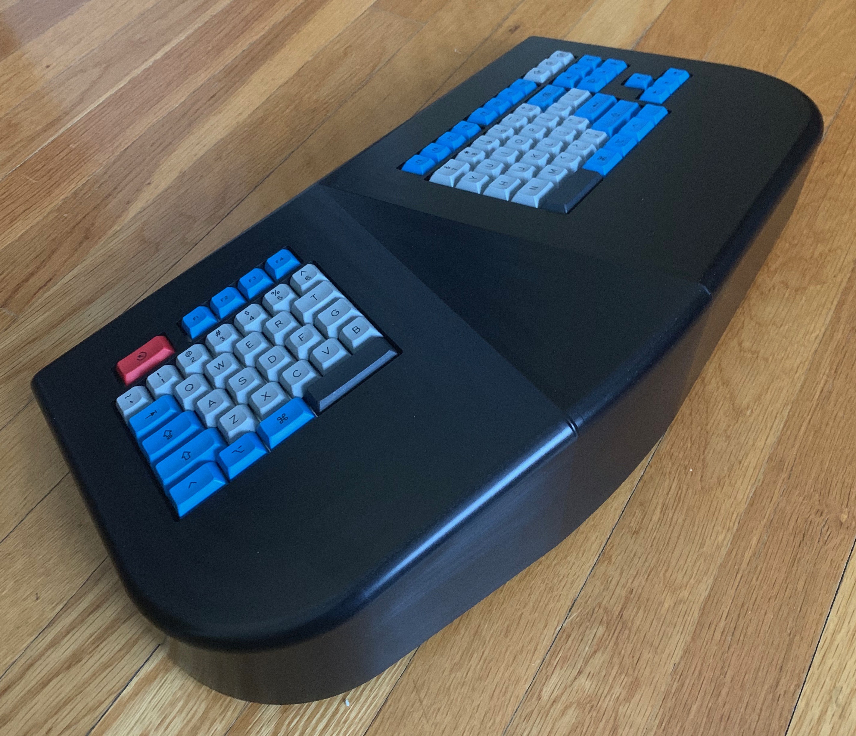
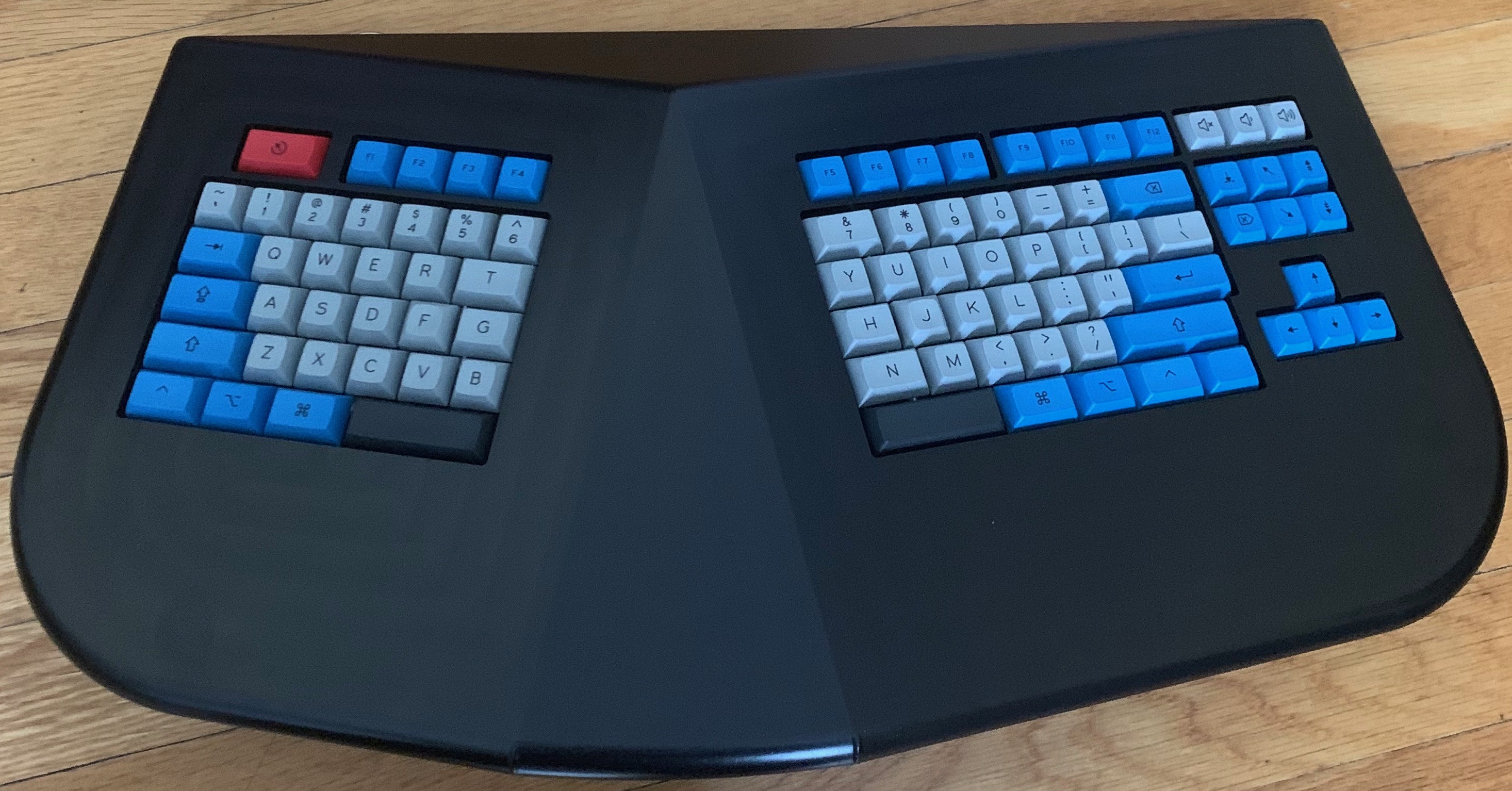
Case design
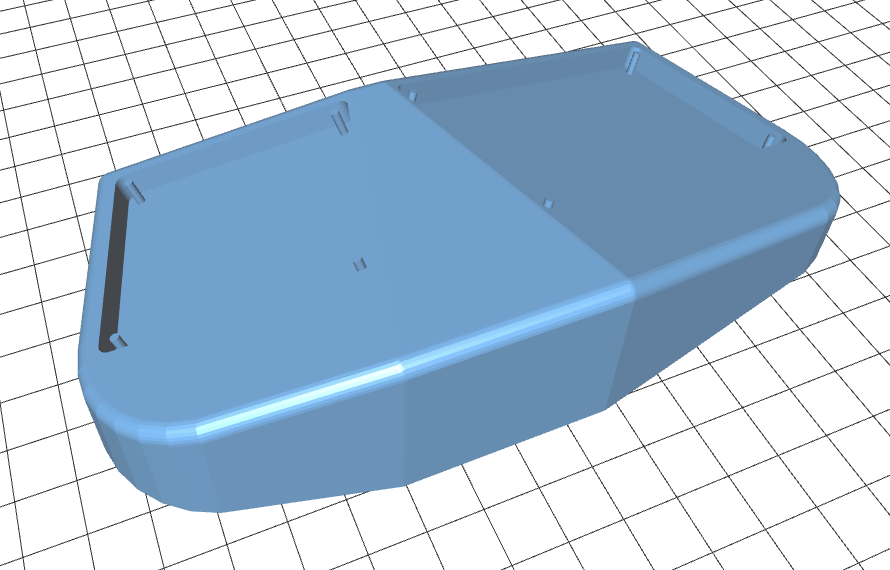
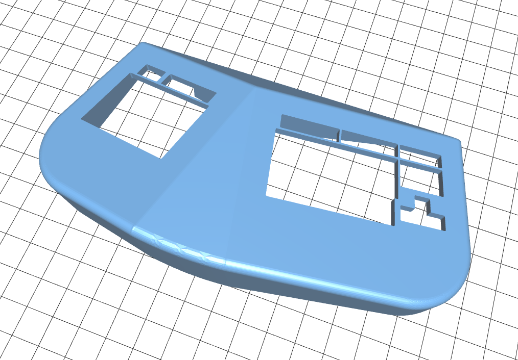
Now that I had a layout I could design the case. Pretty early on I knew that I wanted the keyboard to be a CNCed aluminum case. I envisioned a “bottom-up” design: no exposed fasteners on the top but instead screwing up through a plate mount into the aluminum case with a rubber gasket for damping vibrations and locking the screws.

I used swillkb’s Plate and Case Builder to generate SVG and DXF files from Keyboard Layout Editor files. I made the plates a bit larger than necessary so I would have flanges to screw through. To simplify life I planned on only screwing through the plate: the PCB would only be attached to the switches with solder.
I first started building the case in OpenSCAD because I used it for some simple 3D printed designs before. Though great for simple designs working with multiple rotated planes is difficult in OpenSCAD. Also as I discovered late in the process OpenSCAD only generates STL files which is fine for consumer 3D printers but not what is needed for CNC machines which generally want STEP files.
I still wanted to use a programmatic CAD tool and found CadQuery which uses a FreeCAD as a backend and Python for the frontend. Running CadQuery in Docker was the simplest and most reproducible solution for me. I could edit my Python script and run make to get my STL and STEP files out: a very simple development loop. Using Python opened up a world of useful libraries like NumPy, svgpathtools and pyclipper. The last two were especially important because they let me easily manipulate the SVGs coming from swillkb’s tool.
Thanks to CadQuery it’s simple to pass the various angle of the keyboard (the split, the tilt and the tent) as runtime options and almost always get a working object.
Electronics
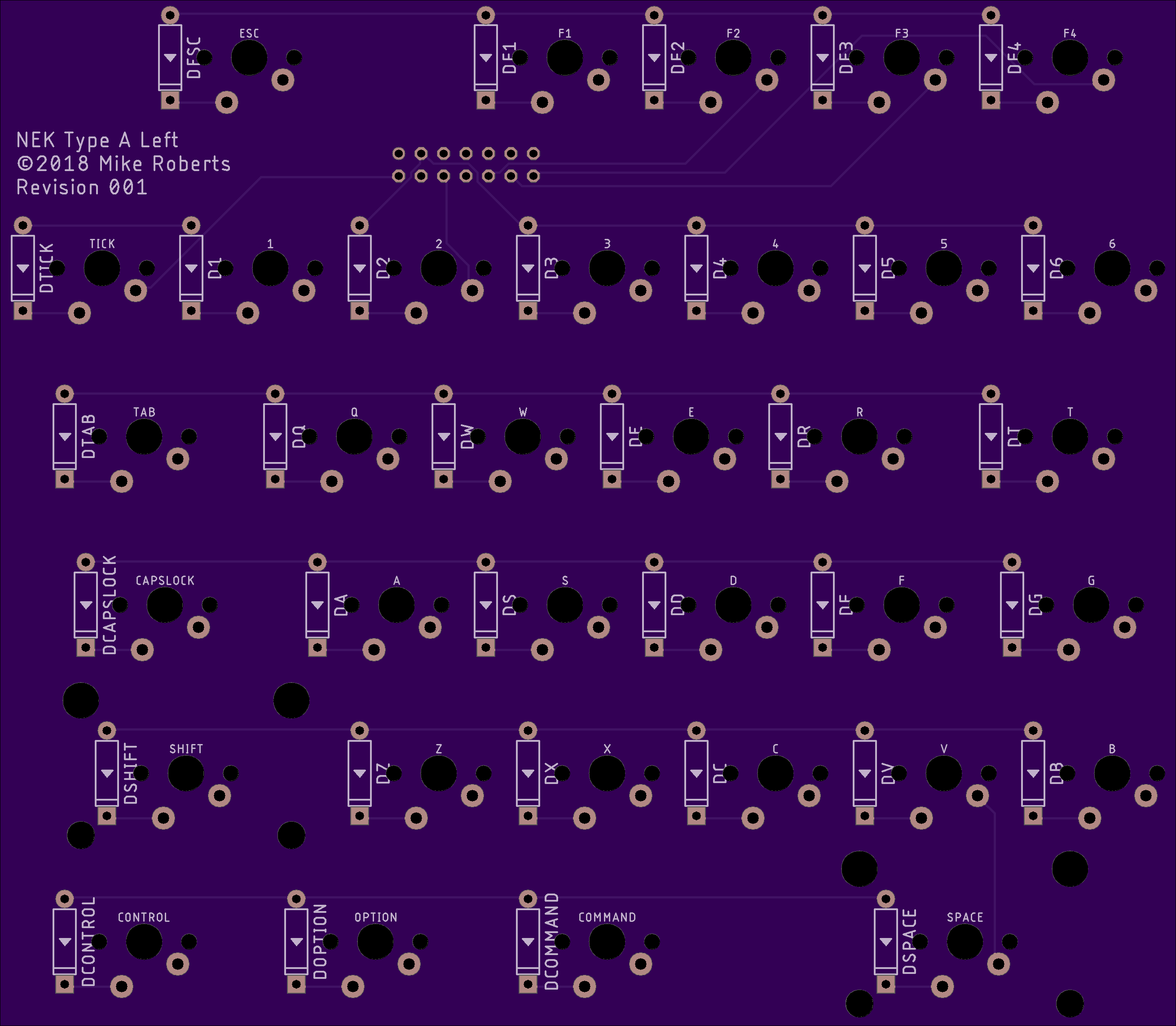
With the case done it was now time to tackle the electronics. I wanted to develop three boards: one each for the left and right halves of the keyboard and then a center control unit connected to the halves with ribbon cables. I wanted to keep the halves with the keyswitches as simple as possible to make future upgrades just a matter of swapping out the center board.
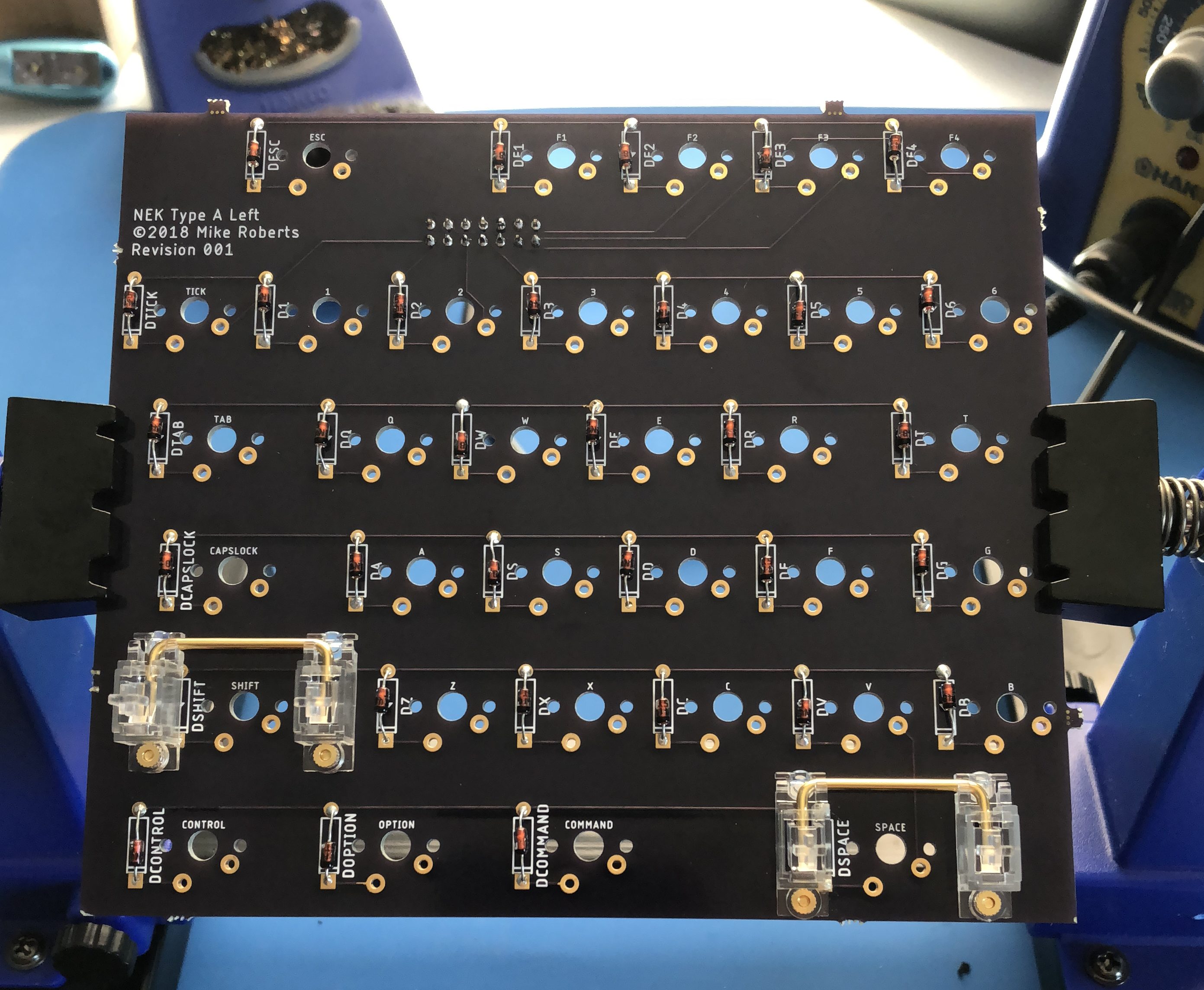
I had no previous experience designing PCBs so I started with Clueboard’s Kalerator. This handy tool takes a layout from Keyboard Layout Editor and generates an Eagle script that gives you most of the layout. This was a very easy way to get the footprints of the keyswitches laid out perfectly. For the left and right boards my only mistake was forgetting about the clearance for the stabilizers on the left board: they overlapped with the diodes for those switches. Luckily its easy to put the diode on the other side of the board.
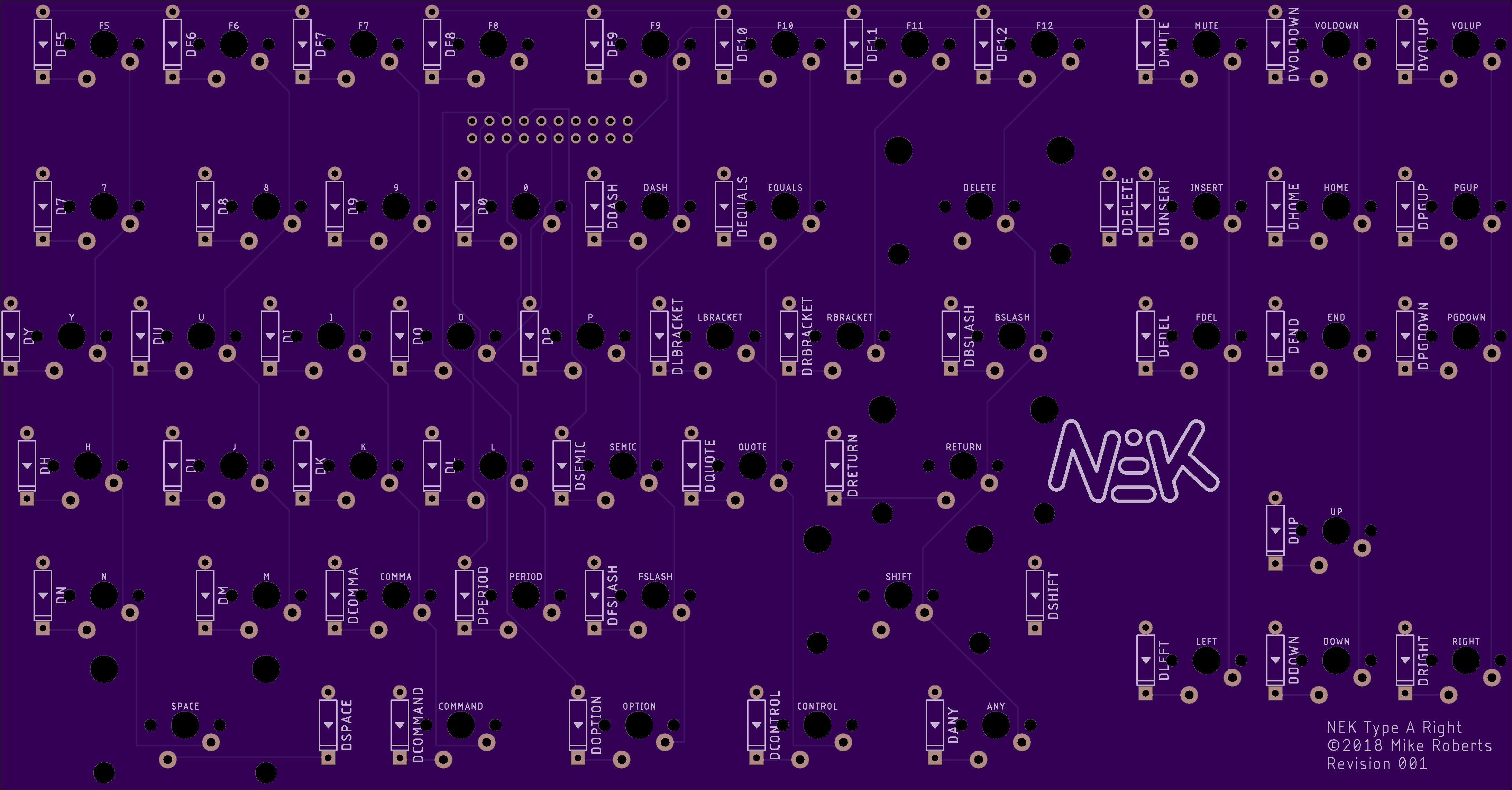
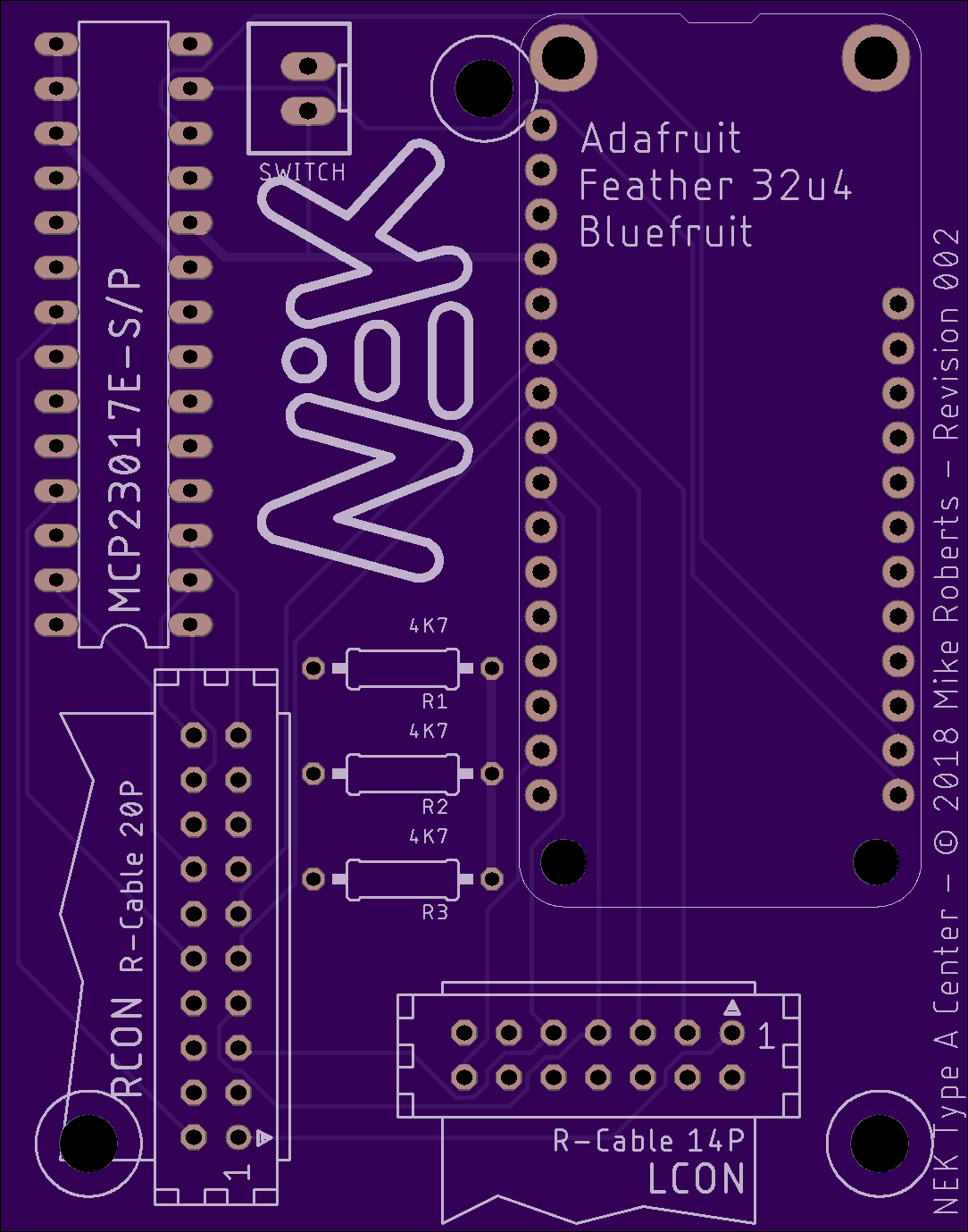
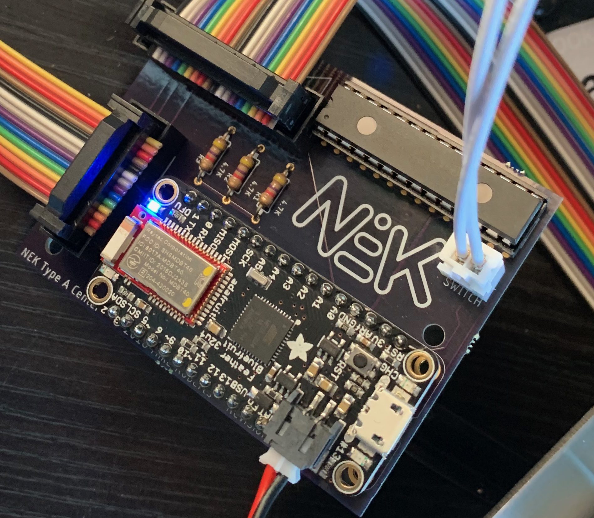
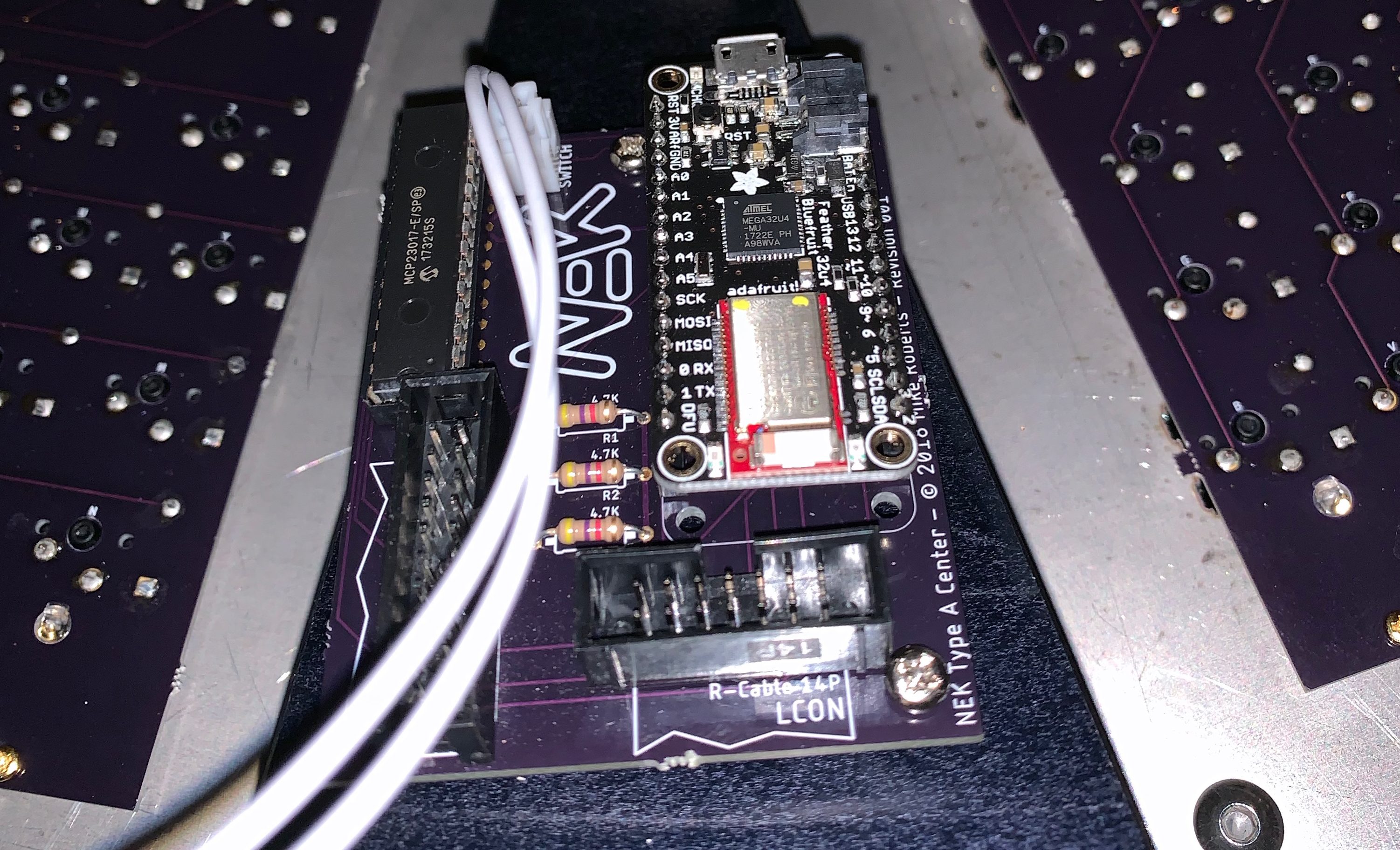
I wanted the keyboard to be able to use Bluetooth or USB connection. I also liked the idea of upgradability and a standardized form factor so I used an Adafruit Feather 32u4 Bluefruit LE as my microcontroller. Instead of soldering it directly to my PCB I would use headers so it is replaceable if I ever need more power. My center PCB is essentially a very weird Feather wing.
The Feather does not have enough pins to support my layout so I connected only my row pins (merging the left and right sides) and the left columns directly. The right columns are connected though a MCP23017E-S/P I/O expander which connects to the Feather via the I2C bus.
I ended up needing to do a second spin of the center PCBs because I forgot about clearance for the three mounting holes and because I used the wrong footprint for the switch connector.
Manufacturing
The keyboard was designed to be easily manufactured. The main components that need to be built and the manufacturer I used are:
- The aluminum CNCed case: Xometry
- The rubber gaskets: Big Blue Saw
- Steel plates: Lasergist
- Acrylic plate: Big Blue Saw
- PCBs: OSH Park
Software
QMK is a wonderful open-source keyboard firmware. It has baked-in support for 32u4 AVRs and supports the Feather (including Bluetooth). I did need to add add support for the IO expander and fork matrix.c to select columns via the expander. My branch of QMK can be found on GitHub.
Assembly
The first step in assembling a NEK Type A is to install the stabilizers on the PCB and then solder on the diodes.
The next step is to install the keyswitches and the case. In the first keyboard I build I used Cherry MX Clears. It’s easiest to start with the four corners so you get a good alignment between the plate and the PCB. After the corner switches are soldered up it’s then just a matter of filling in the rest.
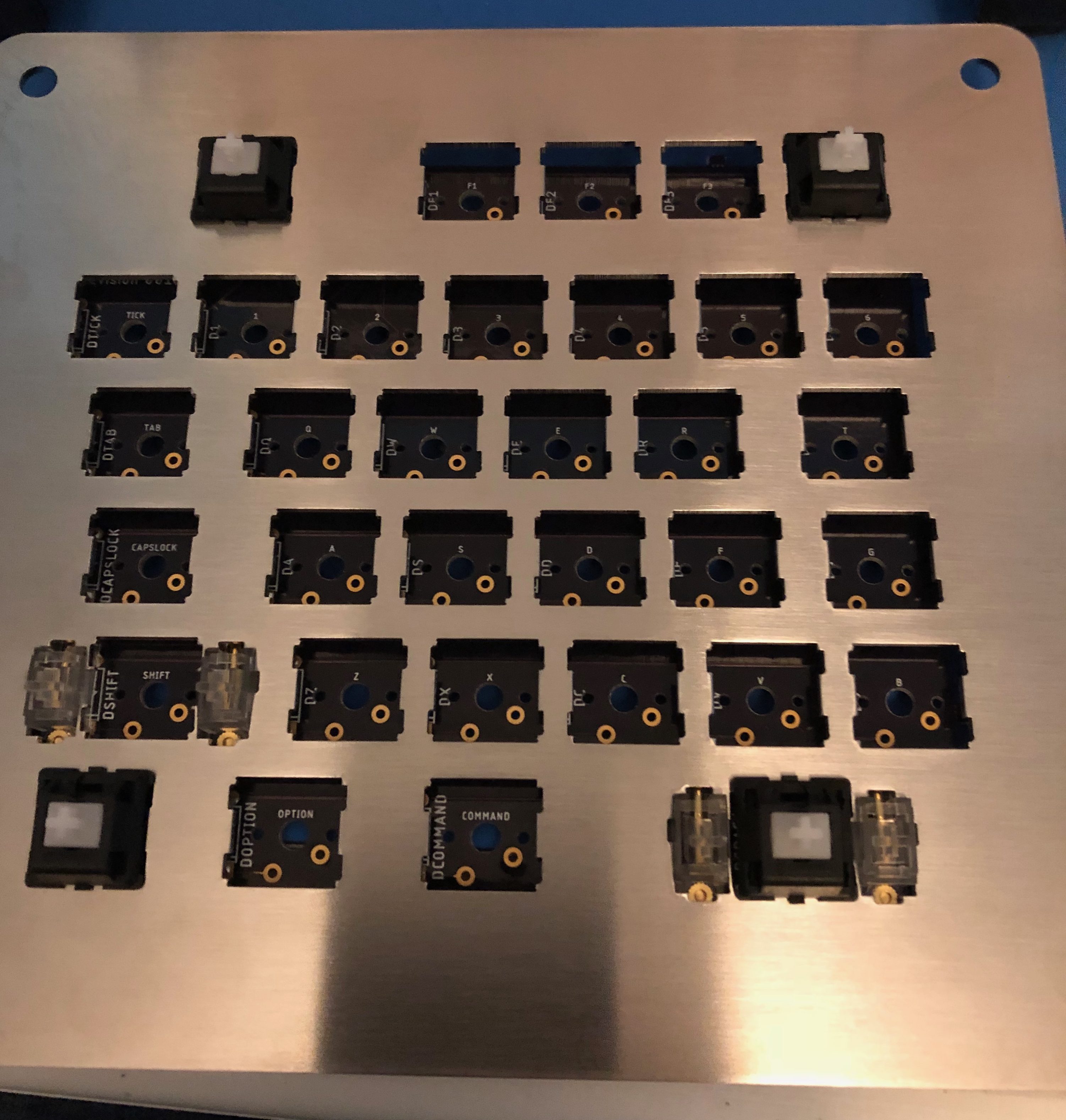
After all the switches for a plate are in place I like to add a set of temporary keycaps. I intentionally left a little slop for attaching the assembled plate to the case because I was unsure of the tolerances of the various manufacturing processes I used to create the sub-assemblies. Having the keycaps on makes lining things up easier.
Next is adding all the components to the center PCB. I generally go from flattest to tallest component when soldering because it makes it easy to use the table to support the component. Note that the I/O expander is intolerant of lot of heat so I use a socket to mount it.
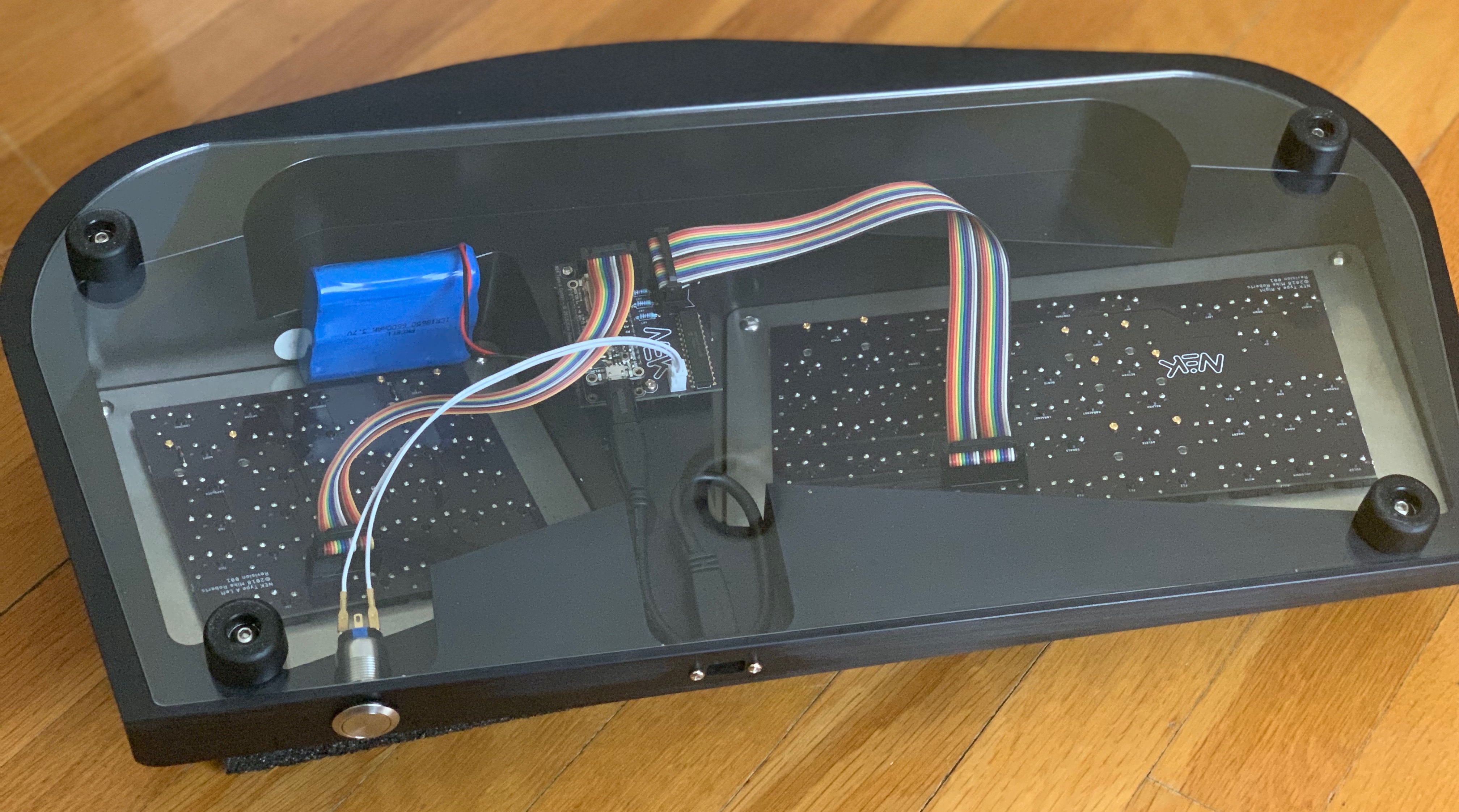
Now it’s time to put everything in the case. The assembled key plates mount with M5 screws with the laser cut rubber separating the steel and aluminum.

The center PCB mounts with M3 standoffs and M3 screws.
Add some custom length ribbon cables, a panel mount USB-C cable, a USB-C to Micro USB adapter, an arcade switch for power, a battery, a laser-cut acrylic panel and some M5 feet and you have a completed keyboard.
Full sources and detailed assembly directions can be found on GitHub.